

Ornithopter
An ornithopter is a type of robot that achieves flight by flapping its wings, mimicking the natural flight mechanism of birds. Unlike traditional aircraft, which rely on static wings or engines, an ornithopter uses the dynamic motion of its wings to generate lift and propulsion, allowing it to fly purely through flapping.
Mechanical
Design/Concept Generation
The concept design for my ornithopter robot focused on simplicity, given my limited circuit knowledge. I created a chassis that could securely house a 9V battery, an ESP32, and a small motor.
To accommodate the size constraints of the 3D printer I would be using, I designed the robot with compact dimensions and produced a bird silhouette sketch approximately 20 cm by 6.5 cm. This approach balanced functionality with practicality, laying the foundation for the final prototype.


Chassis
With no prior experience in SolidWorks, I taught myself the program's fundamentals to create both parts and assemblies.
The sketch was extruded and cuts were made for electronic housing. Specific mounts were designed for easy implementation.
During prototyping, multiple iterations were required to achieve proper fit and functionality.
Current issues: Not enough room for electronics, available space is not optimized

Flight Mechanism
The most critical aspect of my CAD modelling was the recreation of the transverse crankshaft flight mechanism.
Starting from scratch, I designed 10 individual components, modelled them as parts, and assembled them in SolidWorks to confirm functionality.


This mechanism was essential for my ornithopter, as it transformed the circular motion of a motor-driven gear into the linear motion required to make the bird's wings flap. To achieve this, a horizontal rod would be installed to remove the effects of horizontal motion from the gear.
Gear
Shoulder Extension
Should Joint (Half)


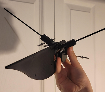
Using rapid prototyping, I 3D-printed my CAD models to create a proof of concept for the transverse crankshaft flight mechanism.
This process verified that the mechanism successfully converted rotational motion into the linear motion required for wing flapping. As the most critical part of the chassis build, confirming its functionality was a pivotal moment in the project.
The redesigned version worked as intended, providing the confidence and foundation needed to move forward with the rest of the ornithopter's development. This achievement highlighted my ability to integrate mechanical principles with CAD modelling to bring a complex concept to life.

Electrical
Circuit Design
Designing the control circuit for my ornithopter involved integrating a brushless DC motor with an ESC to drive the flapping mechanism, while two servos managed tail control for stability and maneuverability. To achieve precise flight adjustments, I incorporated an accelerometer and an IMU, which provides real-time positioning data. The ESP32 served as the central controller, interpreting sensor inputs and coordinating motor and servo responses.
With this in mind, I am currently in the component selection phase for the motor. However, to fully grasp how much power I would need to fly the ornithopter, I'm running a fluid simulation.

Computational Fluid Dynamics
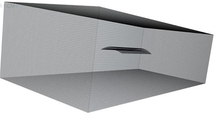
To better understand the aerodynamic performance of my airfoil design, I used computational fluid dynamics (CFD) simulations in STAR-CCM+. This allowed me to analyze the relationship between thrust, velocity, drag, and lift, helping me refine the airfoil’s design for optimal flight efficiency. By modeling the airflow around the airfoil, I aimed to evaluate how different factors influence its performance and make informed design adjustments.
2D Cross sectional view of mesh

3D view of generated mesh
Current Challenges
1. Mechanical:
Although the chassis is complete, it has many problems. One of which, being inefficient with its upwards motion. The shorter rods are too bulky and there isn't enough space on the chassis to house all electronics safely.
To combat these faults, I will:
-
Design a concrete circuit to rebuild the chassis around
-
Re-evaluate the necessary size of the chassis
-
Re-work the flight mechanism to adopt a ball joint instead of the horizontal rods for movement
2. Electrical:
Component selection must be conducted after CFD analysis - currently on hold